Talking about the polynomial order might be ambiguous. In principle, a different degree might be used for domain, model, and wavefield. In Salvus, however, we currently only distinguish between the 'tensor_order', which is the polynomial degree used for the domain and the model, and the degree of the wavefield, which for simplicity, we continue to call 'polynomial_degree'.
Mesh Generation
Generating meshes for efficient waveform simulations in heterogeneous media with complex topography or internal structures has long been considered a difficult and time-consuming task. SalvusMesh is a powerful tool to automate or at least prototype the generation of highly efficient spectral-element meshes.
Throughout this article, we describe requirements, design criteria, and potential pitfalls of generating meshes.
Discrete representations of domains, models, and wavefields
Before Salvus can crunch some numbers, all physics need to be represented by a finite set of values. In particular, there are three different entities that need to be discretized:
| Entity | Description |
|---|---|
| Domain | Outer bounds of the object through which the waves propagate |
| Model | Medium properties that describe how the density and velocity vary within the domain |
| Wavefield | Space- and time-dependent solution of the wave equation |
One can envision each of these entities as something like the following:
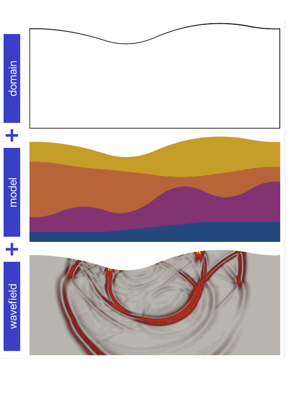
Here, we focus on discrete representations using finite-element meshes of variable polynomial order. Note that the discrete representation of all entities involves polynomials, describing:
- the shape transformation of the elements to characterize the domain,
- the interpolation of the medium parameters for the model, and
- the discrete spatial representation of the wavefield.
Mesh generation tools
Salvus contains many powerful meshing tools that allow for the design of simulation-ready discretizations. Some examples of meshes that Salvus can natively construct include (but are certainly not limited to):
- Rectilinear meshes
- Complex topographic models
- Layered models
- Spherical or spherical chunk domains
- Extrusion of 2D surfaces to 3D volumes
Apart from these native meshing interfaces, it is additionally possible to import external meshes that have been constructed in third-party meshing software. Examples of tools that can be used to construct these types of discrete models (but which do not come bundled with Salvus) include meshing software such as Gmsh or Coreform Cubit.
Quadrilateral and hexahedral meshes
The spectral-element method benefits significantly from the use of quadrilateral (2D) and hexahedral (3D) elements. In fact, the computational penalty of using triangular (2D) or tetrahedral (3D) meshes is so severe that Salvus does not currently allow for users to provide meshes that contain anything other than quadrilateral or hexahedral elements.
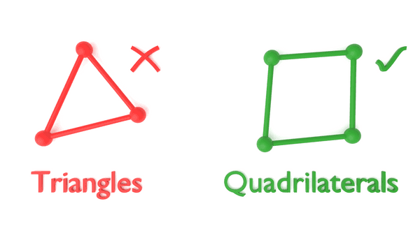
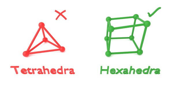
These computational penalties would be incurred with even a single triangular or tetrahedral element within the computational mesh. Thus, hybrid meshes (meshes that consist partly of triangular + quadrilateral elements or tetrahedral + hexahedral elements) are currently not permitted in Salvus.
Conforming interfaces
Interfaces between different materials need to be conforming in order for waves to be able to propagate from one part of the medium to the other. This means that the nodes on one side of the interface must be connected to the nodes on the other side of the interface.
Here's an example of what this looks like:
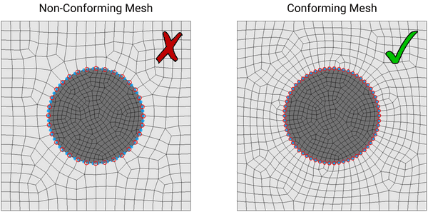
In the above example, the mesh on the left is non-conforming since the nodes on the circular boundary (which separates the white and gray regions) are not shared by both parts of the mesh. That is, the blue nodes on the circular boundary in the (finer) inner region do not coincide with the red nodes on the circular boundary in the (coarser) outer region.
This is in contrast to the conforming case, as seen on the right-hand-side, where the nodes on the circular boundary are shared by both discrete regions. This allows for the transfer of information between both regions, thus enabling the propagation of waves between both areas.
Avoiding overlapping geometry
Geometry that contains overlap between different entities leads to many of the same issues as in non-conforming meshes. In particular, elements between overlapping regions tend not to be linked and, thus, prevent the propagation of waves between these disjoint regions. Here is an example of intersections that one should aim to avoid:

The above mesh, which was constructed using the meshing software Coreform Cubit, should have the two overlapping regions merged in order to ensure that the waves are able to propagate throughout both parts of the domain.
Frequency matters
The highest resolvable frequency — or the shortest period — is the main external driver governing the mesh generation. In order to be able to resolve higher frequency waves, it is necessary to use a finer discretization. However, finer discretizations (i.e., smaller elements in the mesh) generally results in a smaller global time step.
This means that increasing the frequency of the simulation has two effects that increase the compute cost of the wave simulation:
- The mesh must be finer to model the shorter wavelengths. This results in an increase in the number of elements within the mesh.
- In order to ensure stability in the CFL criterion, the time step must also become smaller. This results in an increase in the number of time steps that need to be computed.
Locally constricted elements
A vital consideration that one needs to be mindful of when discretizing the domain is to avoid locally constricted elements. As was noted earlier in this article, the global time step of the simulation is proportional to the smallest element within the domain. This means that if the spectral-element mesh contains even a single element that is abnormally small, one will experience a significant penalty in the global time step.
Here's an example of such a mesh that contains locally constricted elements:
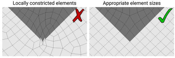
The mesh on the left contains extremely small elements near the tip of the triangle, given that there are exceedingly small features within the geometry that the mesh is attempting to comply with. This mesh would result in a very small global time step for the simulation, meaning that the overall compute cost of performing the wave simulation would increase dramatically.
There are certainly some instances when it is desirable to resolve these types of small features. However, one generally needs to evaluate whether these small features will have any meaningful influence on the resulting wavefield. This is generally a choice that is problem-dependent and must be assessed on a case-by-case basis.
 Mondaic Documentation