Salvus has a number of built-in tools for layered
meshes
and cubed sphere
meshes,
among others. However, there may be some instances where it becomes
necessary to construct a mesh within an external meshing software, which can
then be imported into your Salvus project.
Within this tutorial series, we will review the following points:
- Important considerations to be aware of when constructing discretizations in third-party meshing tools
- How to import external meshes from the Exodus
.efile format - Performing some basic quality control operations on the imported mesh
- Use the mesh in a forward simulation
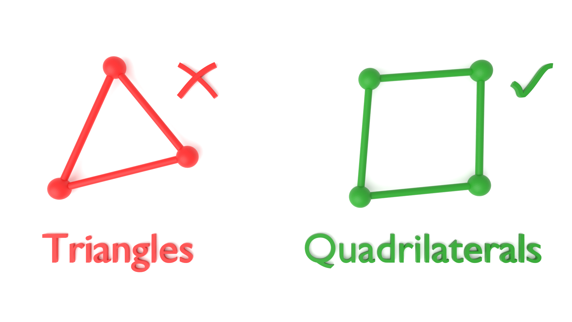
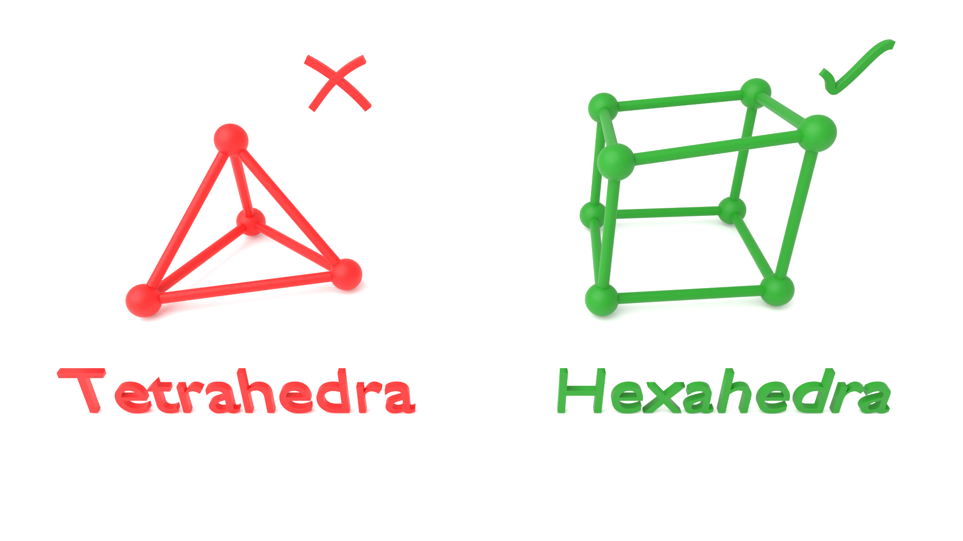
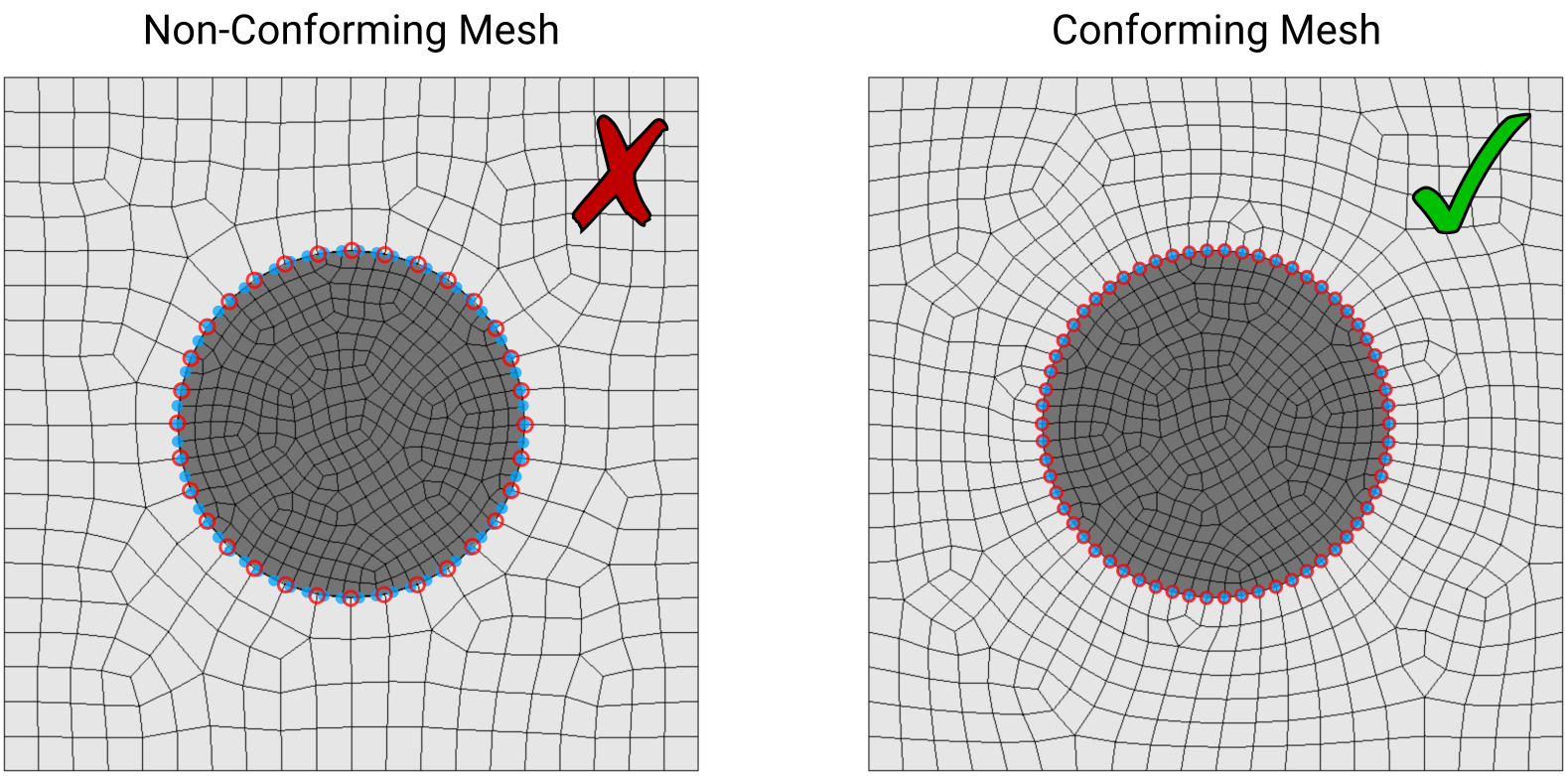
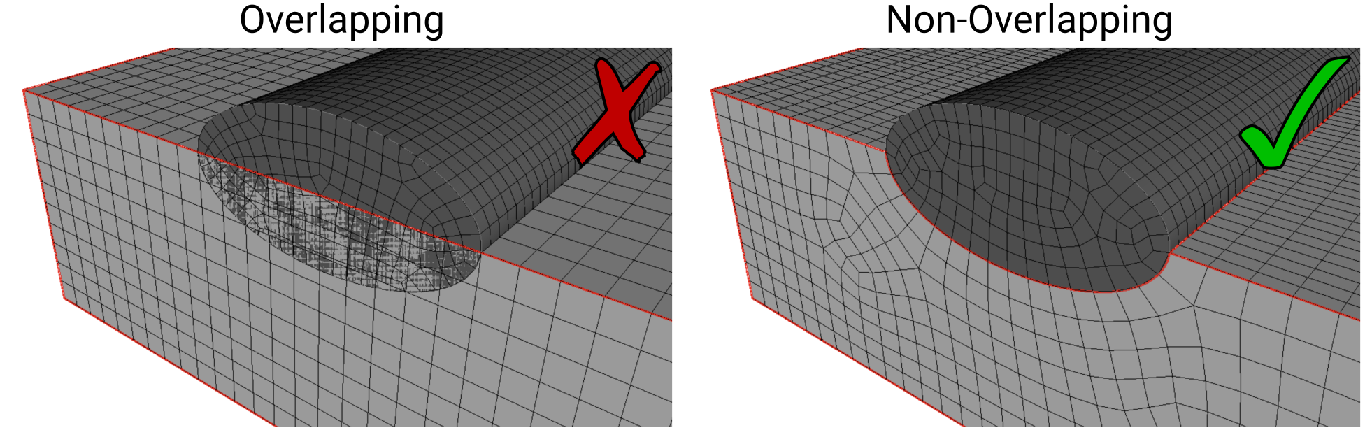
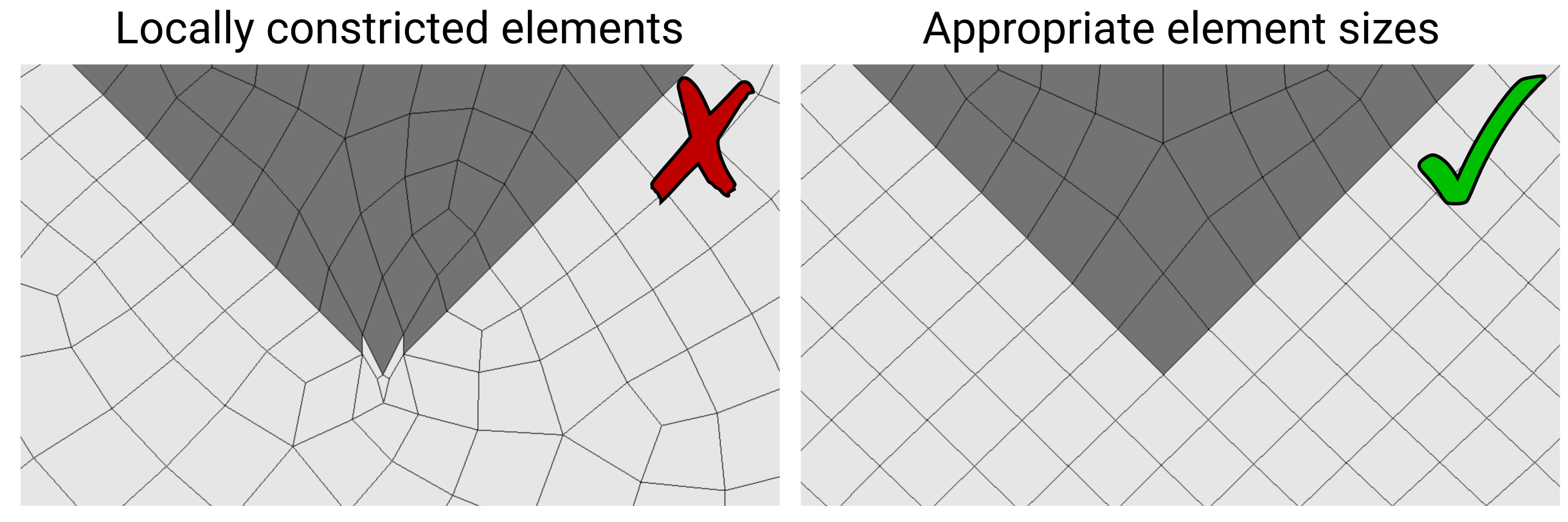
The built-in meshing tools in Salvus are designed to produce simulation-ready
spectral-element meshes. This means that the meshes are constructed in such
a way that they will perform well when used in a wave simulation. However,
when constructing meshes manually using third-party tools, it is up to the
user to ensure the mesh satisfies a variety of criteria:
For more details on best-practices for constructing meshes for use within
Salvus, please see the knowledge base article
here.
The approximate element size required to accurately resolve the wavelengths
in a particular region of the domain can be obtained using
where is the minimum speed of sound in that region of the
domain, is the maximum frequency in the source wavelet, and
are the number of elements per wavelength needed to accurately
resolve the waves. As is discussed in
this
knowledge base article, around 2.0 elements per wavelength tends to yield
excellent results for order 4 simulation (default in Salvus).
The processes for meshing the domains in the accompanying 2D and 3D examples can be skipped by simply using the.efiles that are enclosed with the tutorial.The meshing steps outlined in these tutorials are intended to serve as illustrative examples for how one could go about constructing hexahedral meshes in an external software tool, which will be subsequently imported into the Salvus project later in the tutorial. While these instructions specifically use Coreform Cubit, these steps are equally transferrable to other third-party hexahedral meshing software.
Coreform Cubit is an external meshing
software that allows for the generation of complex quadrilateral and
hexahedral meshes. There are two accompanying tutorials that describe how
one can construct and use these types of external meshes in both 2D and 3D.
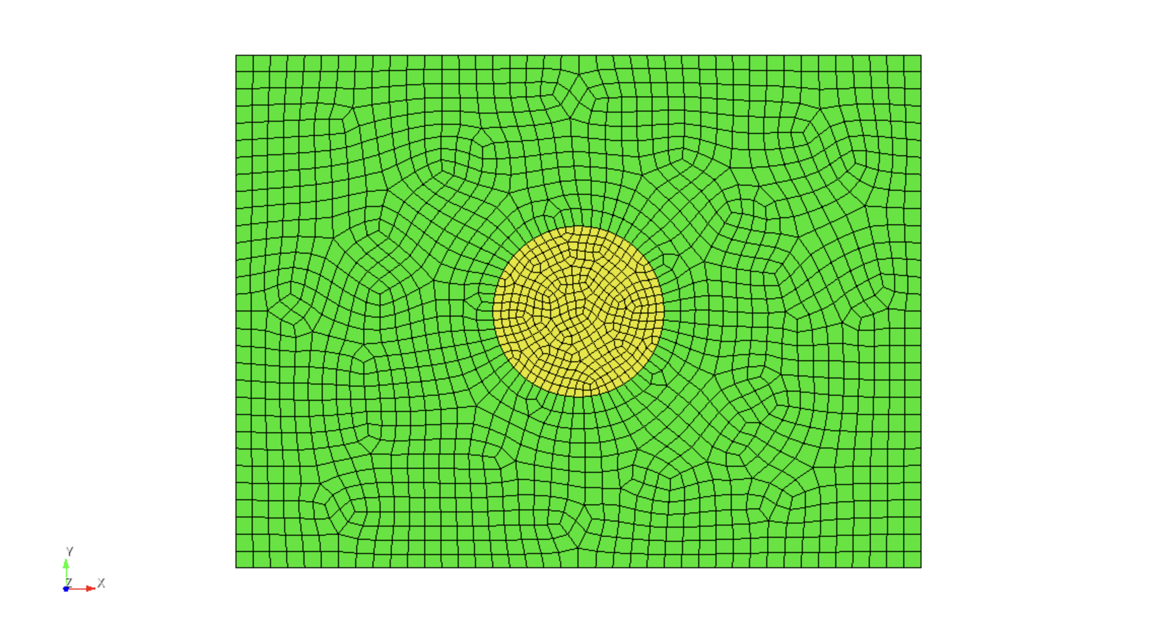
The first tutorial from this series involves meshing a circular inclusion
that is embedded within a rectangular domain. While this geometry is
relatively simple, it illustrates how one can go about generating domains
with multiple distinct materials in 2D.
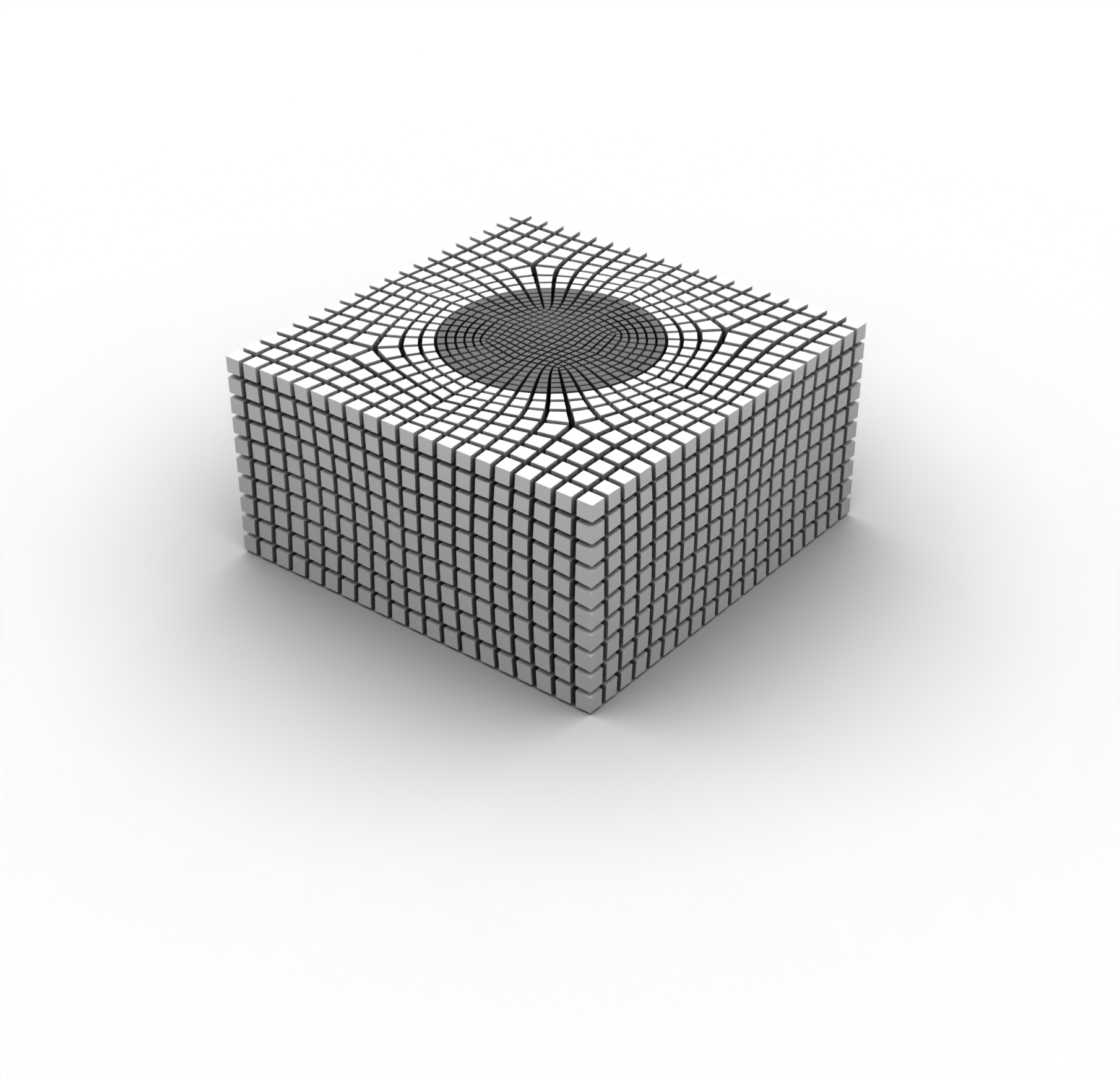
Building off of the approaches showcased in the 2D tutorial, this notebook
provides an analogous workflow for a 3D domain that consists of a hemisphere
embedded within a cuboid. While this 3D mesh is considerably more complex
than that used in the 2D example, the procedure of importing and preparing
the mesh for use within Salvus are nearly identical between the 2D and 3D
cases.

PAGE CONTENTS